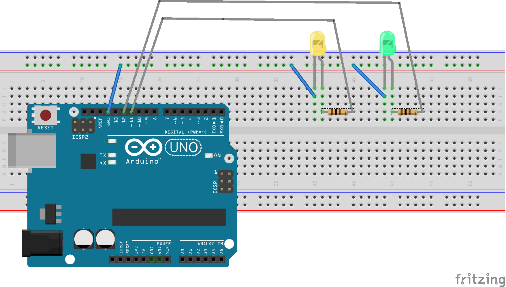

This means that the current sum of all ports should not exceed 200mA. In the case of our ATMega328 it is 200mA. This value is also given in the absolute maximum rating table found in the datasheet. This is the total current that the microcontroller draws from the power supply. Absolute maximum ratingĪ more important parameter that we must also consider is the maximum DC current between Vcc and GND. It is more common for the sink current value to be a little higher than the current source value, in cases where the values are different. Note that for some chips these the values for source and sink are different. This is plenty for a standard LED that will usually run on somewhere between 5mA and 20mA.

Here we can see that the maximum current that we can source or sink on any IO pin is 40mA. Using the ATMega328 microcontroller found on many Arduino boards as an example, we can look this value up in the datasheet available on the Microchip website.

We can only source or sink current up to the maximum amount specified in the datasheet. In either case the load that we are connecting to the microcontroller pin is the LED. When a pin is in its low state (equal to ground, or 0 volts), current will flow from the connected load through the chip and to ground. When a pin is in its high state (usually equal to the supply voltage Vcc) it will supply current to a connected load. Each pin has an absolute maximum amount of current that it is able to source or sink. However there are some other important considerations. If we set them all to an output then the absolute maximum number of LEDs we can control is equal to the number of pins. Your microcontroller has a finite number of pins that can function as a digital input or output. Controlling LEDs Directly with Arduino Digital Pins Let’s take a look at this methods in more detail.
Control led arduino serial#
Control led arduino how to#
As a minimum I would recommend that you have a good understanding of how to control a single LED with Arduino. This article assumes that you are already familiar with some microcontroller basics.
Control led arduino driver#
Some LED driver / shift registers, such as the TLC5917.Arduino compatible board, such as the Arduino UNO.If you want to test out the practical examples in this article, here’s a short list of recommended parts that you will need: Controlling LEDs with Arduino using Multiplexing.Controlling LEDs Directly with Arduino Digital Pins.


 0 kommentar(er)
